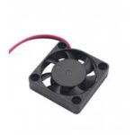
 Our stay in Liechtenstein provided interesting discussions. Especially controlling the FANs of Bart’s (PA3HEA) home made transceiver gave us some interesting food for thought.
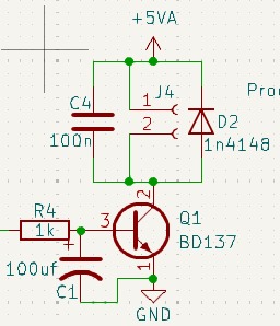
Gert PE0MGB also had used PWM for controlling the FAN speed of his transceiver. He used the following circuit:

That’s not how PWM is supposed to work. At a certain point, the transistor will start to conduct and the FAN wil just turn on. Controlling the speed this way in a smooth way is virtually impossible. Anyway, the FANs did not work. Usually, driving a motor (or a FAN) with a processor is done according to the above schematic, but without the 100uF capacitor connected to the base of the transistor. That results in an amplifier for the PWM pulses from the CPU.
But the FANs still didn’t work.
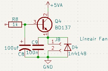
So I tested the FANs on my adjustable power supply. The current draw was 160mA at 5V. Reversing the polarity of the FANs resulted in a current of 220mA but the FANs did not turn. Conclusion: there is some electronics in the FANs. Checking the specifications of the FANs on the internet confirmed that the FANs had a PWM circuit of themselves. And driving that circuit with a PWM signal just dit not work. So I advised to change the circuit as follows:

R8 and C8 make a LPF with a 1.6Hz cutoff frequency. Since the PWM frequency is about 600Hz, the result is a DC voltage on the base of the transistor, which is used as a emittor follower. And now the FANs work and the speed can be controlled by changing the pulse width, which results in a change in DC voltage across the FANs.